Engineering & Manufacturing

Design work from someone who has built the tooling.

I design parts, fixtures, and tooling with the shop in mind, because I have run the machines and built the cells. You get a design your vendor can quote and build without a round of questions.

What I do

Engineering services

Part and assembly design

Parametric parts and assemblies in Autodesk Inventor and SolidWorks, with production drawings to ASME Y14.5.

Jigs, fixtures, and gauges

Weld fixtures, assembly jigs, CNC workholding, and check fixtures designed to be built by local shops.

Press die and stamping tools

Die and stamping tool design from years of building press tooling for production lines.

DFM reviews

Sheet metal, die cast, molded, and machined parts reviewed for draft, wall thickness, bend relief, tolerances, and anything your vendor will push back on.

Automation and cell layout

Robot cell concepts, fixture and end-of-arm tooling layout, and plant layout for the next jump in volume.

Simulation, FEA and lightweighting

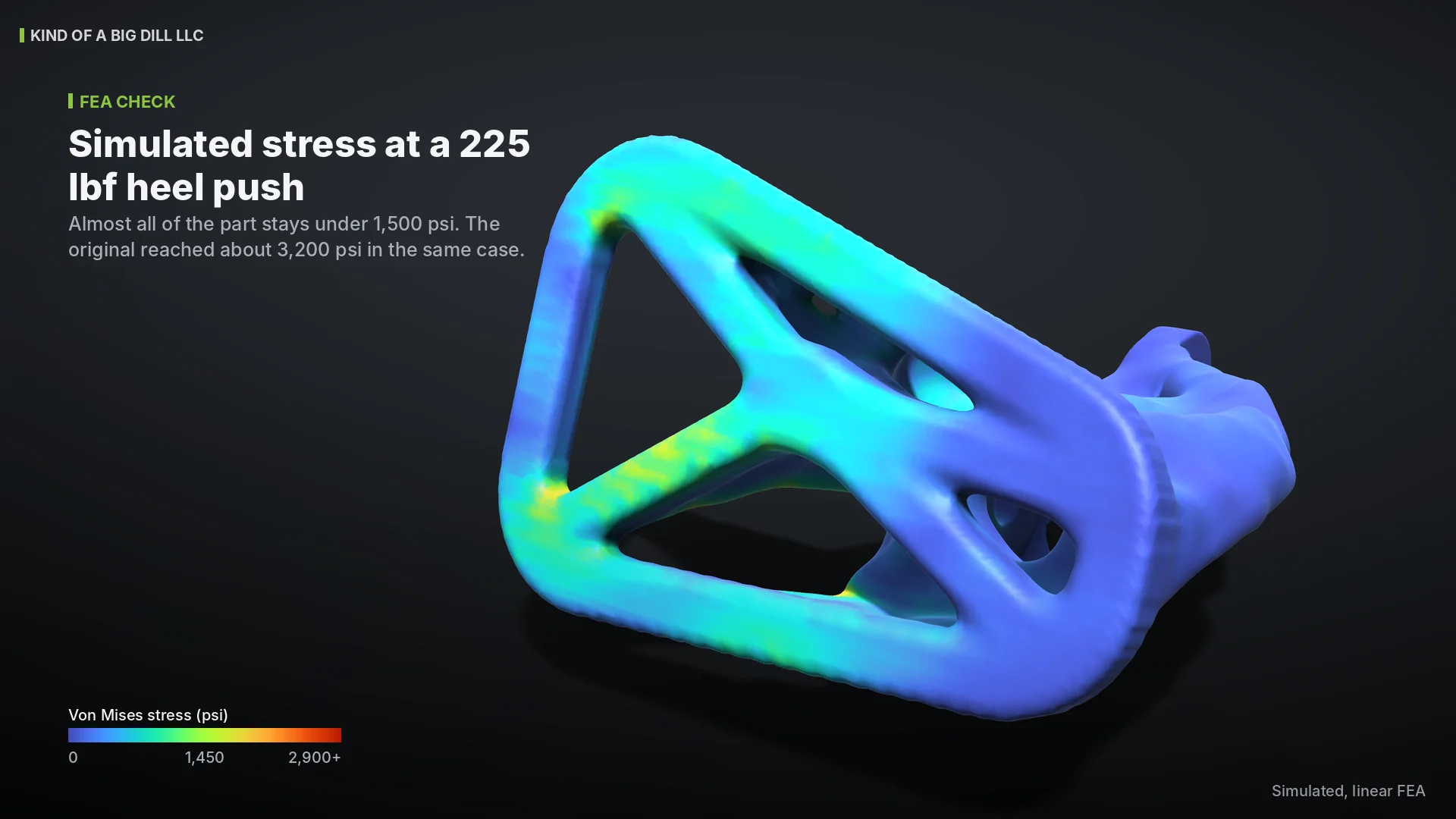
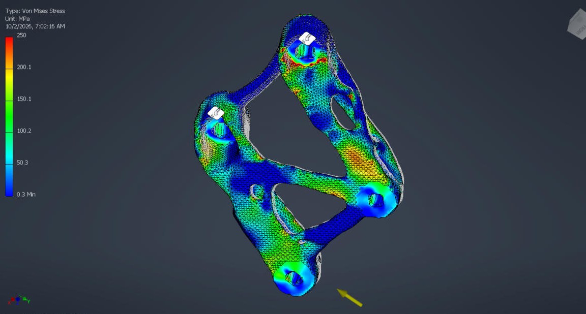
Real load cases, topology optimization and an FEA check on every revision, with the model validated against hand calcs before you see a number. Brackets, plates, arms and printed parts.

Prototypes and small batches

In-house 3D printing for fit checks. Machining, laser, and fabrication through local shops I know and manage for you.

Design for 3D printing

Print-in-place joints, snaps and captive hardware with clearances set for the printer, orientation chosen for the load, and the mesh checked before it ships.

Reverse engineering and scan to CAD

3D scan or measure the part you have, rebuild it as clean parametric CAD, and fix what was wrong with it on the way.
Mechanical design & custom CAD

What custom CAD means when I do it

Modeled for the processDie cast parts get draft, uniform walls and parting lines from the first sketch. Sheet metal gets real bend reliefs and K-factors. Machined parts get tool access and standard cutters.

Parametric and reusableSkeleton-driven assemblies, named parameters, and iLogic rules so the next size or variant is a change of inputs, not a rebuild.

Drawings that survive the vendorGD&T to ASME Y14.5, datum schemes that match how the part is fixtured, and notes a caster or machinist can quote without a phone call.

Proven in productionI have designed press dies and robot cells, run CNC and CMMs, designed metrology systems, and taken products from concept through vendor tooling and first article to launch. Client work gets the same standard.

Simulation and analysis

Load cases in, only the useful material out

Topology optimization finds the load paths. FEA checks every revision. Hand calculations check the model before any of it is trusted. Three recent parts, each with its own case study.
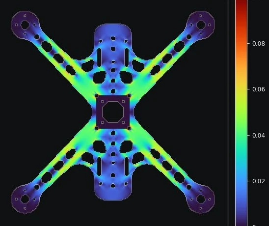
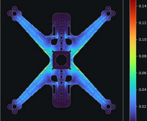
All results are simulated. Material properties are from datasheets or published values unless a case study says otherwise.

Real parts

Inspect a few projects in 3D

Drag to rotate, scroll to zoom, and explode the assemblies to see how they go together.

Camera:
CAD SOLID INSPECTOR
0%
MATED (0%)EXPLODED (100%)
🖱️ Drag to 360° Rotate • Scroll / Pinch to Zoom • Right-Click to PanKBD MULTIBODY DFM VERIFIED
Personal race programNot published

Yamaha R1 Tail Bracket Set

Tail extension, rectifier bracket and ECU tray for my ASRA club race R1 on a Moto Holders race subframe. The tail extension carries the seat bracket and takes the Carbonin tail through rivet nuts.

TECHNICAL SPECIFICATIONS
Material:0.125″ aluminum sheet
Hardware:4x rivet nuts, McMaster 95105A179
Frame:Moto Holders race subframe
Components:Tail extension, rectifier bracket, ECU tray
Case study:kindofabigdill.com/projects/r1-tail-bracket-set
CNC / ADDITIVE STRATEGY:
Flat pattern from the Inventor sheet metal model, cut, then bent to the drawing
Cycle Times: Installed on my ASRA club race bike
ENGINEERING DELIVERABLES
  • ✓Inventor models for the tail extension, rectifier bracket and ECU tray
  • ✓2D drawings with bend callouts and DXF flat patterns
  • ✓Printed fit-check prototypes and a printed ECU tray
  • ✓Parts installed on the bike
Engineering Notes
FROM THE BUILD

DFM: Simple formed sheet metal parts that any laser or waterjet shop with a brake can make from the DXFs.

Deliverables

What you get

Files you ownNative CAD and STEP files, PDF drawings, and DXF flat patterns where they apply.

A short DFM noteAnything your vendor is likely to ask about, answered up front.

One round of revisionsIncluded in every fixed quote.

Honest build partnersI design the tooling and manage the build through shops I trust. I will always tell you who is making your parts.

Have a STEP file or a drawing ready?

Send it over with a short description of what you need. I will reply within 2 business days, and I am happy to sign your NDA first.

Send Me Your Drawing→